
-
Request an Inverter Model Comparison and B2B Quotation
 Short answer: A solar inverter datasheet is not a shopping list of numbers. It is a document. It tells an EPC, distributor or project owner which PV strings, batteries, grid conditions, loads and operating environments a specific inverter can handle. A professional review checks the relationship between the numbers: cold-weather open-circuit voltage against DC voltage hot-weather string voltage against the MPPT window module current against each MPPT input apparent power against power-factor duties, battery current against usable backup power and certification scope against the destination market. If one of those relationships is missing the model is not ready for an order.
This guide explains 25 specifications in the order a technical buyer should review them. It also shows how to turn a datasheet into a RFQ, a factory-acceptance plan and a commissioning checklist. The examples use published THLink Power model-family data where it's clear enough to compare. Every final selection must still use the model-specific datasheet, certificate, firmware statement, wiring diagram and contract schedule.
Send Your Project Data for an Inverter Selection Review
1. The five-minute answer for procurement teams.
Before comparing efficiency or price write down six facts: destination country, grid code, phase and voltage PV module model and string layout, battery architecture if used and the required operating mode. Then check the inverter in this order: topology; AC rating; DC voltage and current limits; MPPT arrangement; grid functions; battery interface; environmental derating; communications; certification; warranty and service. That sequence prevents a mistake: choosing a model because its headline power looks correct while its voltage, current or compliance envelope does not.
A datasheet review should end with one of three labels. Compatible means every critical parameter has been verified against project inputs and supporting documents. Conditionally compatible means the model may work. A named issue such as firmware, certificate coverage, ambient-temperature derating or battery protocol needs written confirmation. Not demonstrated means information is absent or inconsistent. It does not necessarily mean the product is unsuitable; it means procurement should not treat suitability as proven.
Review gate.
Buyer question.
Evidence required.
Common failure.
Application.
On-grid, off-grid, hybrid, backup or export-limited?
Operating-state diagram and control narrative.
A grid-tie model is assumed to provide backup during an outage.
Electrical fit.
Do voltage, phase, frequency and power ranges match?
String calculation, load schedule, SLD, battery schedule.
Nominal kW is compared.
.
Compliance.
Is the model approved for the destination?.
Certificate, report, model list, firmware and grid-profile statement.
A brand-level badge is substituted for model-level evidence.
.
Lifecycle.
Can the buyer. Support the installed fleet?.
Warranty, RMA, spares, monitoring, training and escalation plan.
The purchase price is treated as cost.
.
2. First define the job.
Two inverters that have the same nominal output can serve different jobs. A string inverter that is linked to an utility grid will follow the grid and usually stops energizing the circuit when the grid fails. A battery inverter can create a grid for critical loads. A hybrid inverter can manage PV panels, battery, grid and sometimes a generator.. The word "hybrid" alone does not tell you its transfer time, surge capability, neutral arrangement, black‑start logic or whether it can work without a battery. Start with the job, not the label.
Start with the job, not the label.
Write a one‑page operating philosophy. Name every energy source and every bus. Identify operation, grid outage, low battery, generator start, generator stop, maintenance bypass, emergency shutdown and communications failure. For each state state which loads remain energized who controls power flow and what happens if a command or measurement disappears. This page often exposes scope gaps before hardware is ordered.
A commercial rooftop project may need a three‑phase grid‑tie inverter with zero‑export control and remote monitoring. A telecom shelter may need a solar system that can start independently share power with a generator and recover after deep battery discharge. A warehouse may need peak shaving plus a protected backup panel. A distributor serving North America may need split‑phase output while an EPC, in a 400 V market may need three‑phase operation and a specific utility profile. The datasheet must be read against that operating context.
Record the decision boundary well. Is the supplier providing an inverter, a matched inverter‑battery package or a complete commercial solar system? Compatibility responsibility changes with the scope. If different vendors supply the inverter, battery, energy‑management controller, meter and generator interface the RFQ must identify who owns function and who attends site commissioning.
3. A buyer’s map of the 25 specifications.
No.
Specification.
What it controls.
What to compare it with.
1.
Inverter topology.
Grid‑following, off‑grid, hybrid, transformerless or isolated duty.
Operating. Local rules.
2.
Rated AC active power.
Continuous real‑power delivery.
Load profile, export limit and site temperature.
3.
Maximum apparent power.
Combined active and reactive duty.
Grid-code power-factor and reactive requirements.
4.
Surge rating.
Short-duration load. Backup resilience.
Motor starting current and duration.
5.
Nominal AC voltage, phase and frequency.
Physical. Load compatibility.
Utility, transformer and distribution system.
6.
Maximum DC input voltage.
Absolute PV voltage ceiling.
Weather string open-circuit voltage.
7.
Shutdown voltage.
When conversion. Ends.
Morning/evening string. Auxiliary demand.
8.
MPPT operating window.
Usable tracking range under changing conditions.
Hot and cold string operating voltage.
9.
Number of MPPT trackers.
Independent control of arrays.
Roof orientations, shading and string grouping.
10.
Maximum input current per MPPT/string.
Current. Clipping risk.
Module Isc/Imp, strings and bifacial gain.
11.
Recommended/maximum PV array power.
Permitted DC oversizing.
Yield. Expected clipping.
12.
Weighted efficiency.
Conversion loss across the operating range.
Project. Load profile.
13.
Self-consumption and standby power.
Night and low-power energy use.
Annual. Backup duty.
14.
Power. Reactive capability.
Voltage support and kVA headroom.
Grid. Site penalties.
15.
Current harmonic distortion.
Power quality at the AC interface.
Grid-code. Test conditions.
16.
Protection and grid-support functions.
Safe response to faults and abnormal grid conditions.
Interconnection. Settings.
17.
Battery. Chemistry.
Electrical and control compatibility.
Battery operating. Bms.
18.
Charge/discharge. Power.
Actual storage power, not energy.
Battery limits, cables, protection and duty cycle.
19.
Backup. Transfer time.
Model-family screening table
THLink family Published scope Key values for screening Buyer confirmation TP-GTI Single-phase on-grid, about 1–10 kW 450/500 V DC by model; one or two MPPT; published peak efficiency about 97.3%–98.1% MPPT current, grid profile and exact certificate TP-TL Three-phase on-grid, 4–15 kW 1,000 V maximum DC; 160–850 V MPPT; 400 Vac Derating, export control and local approval TP-EPH / TP-ESS Three-phase hybrid, 4–12 kW 1,000 V PV; 200–850 V MPPT; 130–700 V Li-ion battery range Battery protocol, backup rating and transfer behavior TP-SPI Split-phase hybrid/off-grid, 8 or 10 kW 48 V battery; two MPPT; 125–425 V MPPT range Output configuration, overload duration and destination approval Which loads ride through an outage.
Critical-load. Switching scheme.
20.
BMS and communications protocols.
Data exchange, limits and remote support.
Battery make, EMS and cybersecurity policy.
21.
Ingress protection.
Resistance to dust and water entry.
Mounting. Exposure.
22.
Operating. Derating.
Available output, in heat or cold.
Site ambient, gain and ventilation.
23.
Altitude, cooling and acoustic data.
Thermal margin, maintenance and siting.
Elevation, dust, noise limit and service access.
24.
Dimensions, weight and terminals.
Handling, wall strength and cable entry.
Installation drawing and logistics plan.
25.
Certification, warranty and service.
Legal. Lifecycle support.
Exact model, country, issuer and contract terms.
Do not turn the table into a box-ticking exercise. Several parameters interact. Reactive-power duty can reduce active-power headroom. High ambient temperature can derate output below the nameplate rating. Parallel PV strings can satisfy a power limit. Exceed MPPT input current. A battery may have kilowatt-hours but not enough discharge power to start a motor. The remaining sections show how to test those relationships.
4. AC power is more than the kW number.
Rated active power is normally the real power an inverter can deliver under stated conditions. Buyers should look for the reference temperature, voltage and power factor. If the project sits in an electrical room or at high elevation the available continuous power may be lower. Ask for the derating curve than assuming the nameplate applies to every hour of the year.
Apparent power, expressed in kVA combines reactive duty. This matters because modern grid codes may ask an inverter to supply or absorb power, support voltage or remain connected through abnormal conditions. If a 100 kW inverter has limited kVA headroom, an instruction to operate away from unity power factor can reduce the power it can export. Put the expected reactive-power envelope in the energy model and the acceptance test.
Overload and surge ratings require a time axis. "Two times surge" is incomplete unless it says for how milliseconds or seconds at what voltage and under what temperature. For an on-grid plant surge capability may be less important than grid support. For backup or off-grid duty it can determine whether compressors, pumps, fans or transformers start reliably. Ask for a load-starting study using measured or manufacturer-supplied inrush data.
Voltage, phase and frequency must match the connection point. Check whether the published voltage is line-to-line or line-to-neutral whether a neutral conductor is required and whether the model supports phase, three-phase or split-phase service. Confirm the operating range, not just the nominal value. For generator-assisted systems compare the generator’s voltage and frequency behavior with the inverter’s acceptance window and control logic.
The purchase schedule should state power, apparent power, phase arrangement, rated current nominal voltage, frequency, power-factor range and all applicable derating. That schedule is more useful than a marketing statement such, as " grade " because it can be tested at the factory and site.
5. DC voltage: calculate the hottest string.
Maximum DC input voltage is the possible limit, not a goal. The voltage when the module is not connected increases as the temperature of the cells goes down. The person who designs the system needs to find out the possible voltage for a group of modules connected together. They need to use the modules temperature factor, the possible temperature for the cells how many modules are connected in a row and any extra safety space that is needed for the project. If this number is higher than what the inverter can handle the group is not safe even if it works fine on a day.
The MPPT window is the range where the system can control the power from the panels close to the best point. The voltage of the module goes down when it is hot. The lowest voltage for the power point at the temperature should still be inside the range where the system can work properly after considering the loss in the cables. The voltage when it is cold should also be inside the limit of the tracking range. That is why an inverter that can take up to 1,000 volts might not be the choice for a certain number of panels. The highest limit and the tracking range have jobs.
The start and shutdown voltage affect how the system works in the morning and late afternoon but they should not be looked at on their own. A low start voltage does not mean the system will get a lot of power when the sunlight is very low. Other things like power use how the tracking system works, the minimum power needed and how the panels are arranged all matter. People who are buying should use a simulation or a tested design tool and then look at the expected energy over the whole year—not just focus on one low start point.
Ask the people who are bidding to provide the calculation for the string as a document. It should include the version of the module the version of the inverter the highest temperatures used in the design the temperature factors how many modules are in a string how many strings are connected to each MPPT the calculated voltage at open circuit and at the power point and the assumption about the voltage loss in the cables. If the bidder can't do the calculation again their offer is not good enough.
6. The number of MPPTs and the input current decide how the roof can be connected.
An MPPT tracker manages the power point of the strings connected to it. More of these trackers can help if the panels face ways have different angles or are shaded differently. The key word is independent. Having connectors does not always mean more trackers. Look at the drawing. Make sure which connectors are connected to the same MPPT channel.
The maximum input current for each MPPT and the maximum short-circuit current are two limits. The first one is about working. The second one is about the current that the system can handle safely if something goes wrong or during testing. New current and panels that collect light on both sides make this check important. Calculate the current using the module information the number of strings the extra power from the back side if needed and the current multiplier or safety factor, for the project. Do not use the wattage of the module of the current.

Unequal strings on a tracker can cause mismatch and tracking problems. I recommend keeping the module type, string length orientation and shading behavior the same within each MPPT unless the inverter documentation says otherwise. If a roof has east and west sides using trackers is often helpful. If one side is shaded a lot by a penthouse the design may need grouping, fewer modules or module‑level electronics.
Ask the bidder for a string‑to‑MPPT schedule. That schedule should show every input, string ID, module count, array direction, current and voltage. The schedule must match the single‑line diagram, cable schedule, labels and monitoring configuration. During commissioning technicians can use that schedule to compare measured string voltage and current with the design.
7. PV oversizing, DC/AC ratio and clipping.
The ratio of PV array DC nameplate capacity to inverter AC capacity is often called the DC/AC ratio or inverter loading ratio. A ratio above 1.0 can be entirely rational because modules rarely operate at nameplate power for long. Extra DC capacity can improve utilization during lower‑irradiance hours but it can also increase clipping, thermal loading and current stress. There is no best" ratio.
The U.S. Department of Energy’s current PV cost benchmarks show that different system types use inverter loading ratios; the published reference designs include values around 1.14 for a residential microinverter example 1.20 for a commercial system and 1.34 for a utility‑scale example. Those are benchmark configurations, not a prescription for another country or project. The correct ratio depends on irradiance orientation, temperature, module degradation, export limits, energy value by hour warranty conditions and the inverter’s current and power limits.
Ask for a simulation that reports clipped energy separately. Then compare the value of the harvested energy with the cost of additional modules, mounting, cabling, labor and possible export. A system with modules and valuable morning or afternoon energy may justify a higher ratio. A zero‑export site with low weekend demand may not. For a design the controller and coupling architecture determine whether energy that would otherwise clip can charge the battery.
The datasheet may publish " recommended PV power." Treat that as one constraint, not the design. The array must still satisfy voltage MPPT voltage, input current short‑circuit current, connector, thermal and warranty rules. Put the approved DC/AC ratio. Modeled clipping percentage, in the design basis so a later module substitution cannot change them silently.
8. Efficiency figures need test conditions.
Peak efficiency is the conversion point achieved under specific laboratory conditions. It gives a number but it does not reflect how the system performs over a full year. Weighted efficiency takes into account part-load conditions using a defined weighting. This may better match a climate or test standard. Buyers should make sure to know which weighting method is used and avoid comparing a peak efficiency value from one model with a weighted efficiency value from another.
Annual energy output depends on factors: MPPT behavior, standby power use, thermal derating, clipping losses, transformer loss, cable loss, auxiliary power, shutdown thresholds and availability. Even a small difference of a tenths of a percentage point in headline efficiency can matter at scale.. A mismatched MPPT window or frequent high-temperature derating can have a bigger impact. Build a model that includes the chain of losses.
For storage inverters ask whether the published efficiency refers to one-way conversion or round trip through both the inverter and the battery. Battery round-trip efficiency changes based on power level, temperature, state of charge and age. If a supplier shows one attractive number request the full efficiency curve and the test boundaries. When comparing AC-coupled and DC-coupled systems clarify where the measurements start and end.
Standby and nighttime consumption should be included in the energy model for small off-grid setups or for systems deployed in large numbers. Find out what powers communications and control electronics during the night. Does the unit go to sleep? How does it wake up? What happens to monitoring while its asleep? In a mini-grid even a small continuous auxiliary load can drain significant battery energy over long nights.
9. Grid functions and certification are specific to each model.
Grid-connected inverters must do more than just produce sine-wave current. Depending on the location they might need -islanding protection, voltage and frequency ride-through capabilities, reactive-power control, active-power curtailment, ramp-rate control, power-quality limits, export control and remote communications. IEEE 1547 covers interconnection and interoperability requirements for distributed energy resources in 60 Hz markets. IEC 61727 addresses utility interface characteristics for grid-connected photovoltaic systems. These standards do not replace utility rules, application processes or settings approvals.
Safety standards also play a role. IEC 62109 sets safety requirements for PV power-conversion equipment, including protection against hazards, thermal risks, fire hazards, mechanical issues and others. UL Solutions lists UL 1741 as one of the standards, for inverters, converters, controllers and interconnection system equipment used in distributed energy systems. A buyer should ask for the certificate, the issuing body, report or certificate number, model list, edition and any national deviations.
A certificate logo on a brochure is not enough. Verify that the quoted suffix, hardware version, firmware, power rating and destination grid profile are covered by the document. Ask if changes to firmware or critical components need a certificate. If a distributor will private‑label the unit clarify how the original certificate holder, the label and local registration are connected.
The RFQ should identify the party that will select and lock grid settings prepare utility documents attend witness tests and correct nonconformities. Product certification shows assessed capability; it does not automatically prove that the installed plant, protection, meter, transformer and settings will pass every site test.
10. Power quality, power factor and export control.
Check the inverter’s reported harmonic distortion and the conditions of that measurement. A low figure at rated power may not describe very low‑power operation. The project‑level limit may apply at the point of coupling, where background distortion and other loads matter. If the site has variable‑speed drives, welders, large UPS systems or weak‑grid conditions a power‑quality study may be appropriate.
Show the power‑factor range and reactive‑power capability as a curve or operating envelope when possible. Ask if full active power remains available at the required power factor. Confirm the supported control modes: fixed power factor, fixed reactive power, volt‑var or utility‑commanded operation. State who provides the meter or controller used for closed‑loop control.
Zero‑export control needs an end‑to‑end response time, not an "export limit" feature. The meter must measure the point communications must be reliable the controller must react quickly enough and the inverter must follow. Define the transient export and the response to meter loss, network loss or controller failure. Some projects must fail safe by reducing output; others may trip. The local authority decides what is acceptable.
For inverters ask if one plant controller can coordinate the fleet and if firmware versions must match. Confirm data resolution, command priority and the interaction, between export control, battery charging, generator operation and demand management. A system can meet each requirement separately yet behave poorly when several control loops compete.
11. Inverter specifications: energy and power are different.
Battery capacity is measured in kilowatt-hours. Inverter charge and discharge capability is measured in kilowatts or amperes. A 20 kWh battery connected to a 5 kW inverter can theoretically provide four hours at 5 kW if there is no reserve and no losses. It cannot become a 10 kW backup source just because there is energy stored. Similarly a high-power inverter cannot create autonomy, from a small battery.
Check the allowed battery-voltage range based on the battery’s state of charge and temperature limits. Voltage 48 V systems require high current when delivering high power. Cable size, breaker rating, terminal temperature and voltage drop are factors.High-voltage battery systems reduce current for the power but require balanced series architecture, proper insulation, switching and BMS coordination. Never use the battery voltage instead of the working range.
The solar battery supplier and the inverter vendor should give a written compatibility statement that lists the battery model, BMS firmware, inverter model and inverter firmware. Make sure to check CAN or RS485 protocol, termination, cable pinout, current-limit behavior alarm mapping, charge-voltage control and what happens if communication fails. Saying "supports lithium batteries" is not an integration statement.
For backup record continuous backup power, short-duration overload, transfer time, phase balance, neutral and earth behavior black start, minimum battery state of charge and the restart sequence. Sensitive process controls may not accept a transfer that household appliances can handle. Motors and transformers might need surge power than the datasheet’s continuous value suggests. Test the critical-load panel during site acceptance.
12. Generator integration requires a control plan.
A generator input label does not mean that all generators will work properly with the inverter. Compare voltage, frequency, phase, minimum loading allowed power, ramp rate and short-circuit behavior. Decide if the generator supplies power directly charges the battery through the inverter. Does both. Say if PV stays online when the generator is running and who controls the bus.
Generators can become unstable when they are lightly loaded and strong battery charging can overload them. A supervisory controller may need to limit charge power depending on the available generator capacity and current loads. The start and stop logic should include battery state of charge forecasted load, minimum run time cooldown failed-start alarm and manual control. Fuel availability and maintenance are still part of the system’s reliability.
During commissioning test a sequence. First the battery reaches the start threshold. Then the generator receives a start command. After that voltage and frequency stabilize. Next the inverter accepts the source. Then. Charging increase gradually. PV contribution changes. The battery reaches the stop threshold. Charging tapers. Finally the generator cools down. Stops. Log power, voltage, frequency, state of charge, alarms and transfer events.
For projects, document recovery after a complete shutdown. Which device has power? Can the battery BMS wake the inverter? Can the inverter start from PV? Can the generator start without site staff? Even if a system operates well while energized it may still fail its important test if it cannot recover after a long outage.
13. Environmental ratings: IP is one line.
Ingress‑protection ratings describe resistance to objects and water under defined test conditions. They do not by themselves address corrosion, condensation, ultraviolet exposure, salt mist, insects, chemical atmosphere, flooding, direct sun or poor cable‑gland installation. Match the enclosure and installation method to the site. A high IP rating can be defeated by glands, missing seals or open conduit paths.
Review the operating‑temperature range and the derating curve. The inverter sees air temperature plus heat from sunlight, neighboring equipment and restricted airflow. A metal enclosure in sun can be much hotter than the weather forecast. If the manufacturer specifies shade or clearance show it on the installation drawing. For hot‑climate projects compare output at the expected worst‑case temperature not at 25°C.
Altitude can reduce cooling effectiveness and insulation margin. Ask when power or voltage derating begins. Cooling design affects maintenance: fan‑cooled models may need filter cleaning or fan replacement while natural convection demands airflow. Acoustic data matters, near offices, homes, hotels, schools or clinics. Confirm whether noise is measured at a stated distance and operating point.
Weight influence freight, lifting, wall strength, access and replacement. Request the installation drawing before finalizing the room. Check top, side and front clearances; cable bend radius; gland plate; isolator access; display visibility; and the space needed to remove covers. A product that fits on a plan may not be serviceable after switchgear and cable trays are installed.
14. Communications, monitoring and cybersecurity.
Monitoring should support operations not just create a dashboard. Decide which values are needed: DC voltage and current by MPPT, AC power, grid voltage and frequency, energy, temperature, battery state, alarms, event logs, export status and communications health. Set how often data is sampled and stored. Decide who owns the data, who can export it and how long it is kept available.
Common physical and application interfaces are RS485, CAN, Ethernet, Wi-Fi, cellular gateways and vendor cloud platforms. Make sure to confirm the protocol and register map. Saying "RS485 available" does not mean it is Modbus compatible. If the site uses SCADA or a building-management system ask for the point list and integration method before shipping.
Connected inverters are part of technology. Ask how accounts are created who can change settings from afar if multi-factor authentication is available how firmware is. Updated, how vulnerabilities are reported and if remote access can be turned off. Create installer, operator and administrator roles if the platform allows. Remove default passwords during setup. Note account ownership during handover.
Plan for cloud issues. Local protective features must stay safe. The site must still have access to important alarms and data. If export control uses a meter and controller check that it does not depend on the public internet. Document what happens after a router failure, gateway failure, time-sync loss and when things come back.
15. Reading THLink Power model-family data without mixing models.
THLink Power has a published inverter catalogue with architectures. The table below is a summary, not a replacement for the up-to-date model-specific document. It helps buyers see which family is worth a look. Any confusion should be turned into an RFQ question of an assumption.
Family.
Published scope.
Key published values.
Suitable screening use.
Buyer must still confirm.
.
TP-GTI.
Phase on-grid around 1–10 kW.
450/500 V maximum DC depending on model; 1 or 2 MPPT; published peak efficiency around 97.3%–98.1%.
Residential and small commercial grid-tie screening.
Exact MPPT current, grid profile, certificate and environmental rating.
.
TP-TL.
Three-phase, on-grid 4–15 kW.
1,000 V maximum DC; 160–850 V MPPT range; 400 Vac; published peak efficiency around 98.0%–98.4%.
Commercial. Light-industrial grid-tie screening.
Tracker count/current presentation, derating, export control and local grid approval.
.
TP-EPH / TP-ESS.
Three-phase hybrid, 4–12 kW.
1,000 V PV; 200–850 V MPPT; two MPPT; 130–700 V Li-ion battery range; 25 A charge/discharge shown.
Three-phase PV plus storage screening.
Battery compatibility, backup rating, transfer behavior and certificate scope.
.
TP-REVO HES.
Single-phase hybrid, 6 or 8 kW.
550 V maximum DC; 90–450 V MPPT; 40–58 V battery; lithium or lead-acid listed.
Voltage residential storage screening.
Usable. Discharge power, battery protocol and backup-load limits.
.
TP-SPI.
Split-phase hybrid or off-grid 8 or 10 kW.
48 V battery; two MPPT; 125–425 V MPPT; 500 V open-circuit voltage per listed input; published peak ratings of 16 or 20 kW.
Split-phase and high-surge residential or remote screening.
Exact output voltage configuration, overload duration, parallel rules and destination approval.
.
TP-HF.
Single-phase on or off-grid hybrid 5–12 kW.
48 V battery; 80–450 V MPPT; 500 V maximum PV open-circuit voltage; one or two trackers by model.
Residential and light-commercial low-voltage storage screening.
PV current, battery current, operating modes, transfer behavior and certification.
.
Two cautions are important. First catalog tables can contain formatting errors. Treat rows as questions to resolve with the latest signed datasheet. Second family-level statements must not be applied to every suffix. A certificate, enclosure rating, communication option, overload rating or grid function may vary. Put the approved model code and revision in the purchase order.
For a comparison with a solar inverter supplier send the same project sheet to every bidder. Include country, grid code, phase, voltage, frequency, module datasheet, string count, PV capacity, ambient range, altitude, battery details, critical-load schedule, quantity, delivery date and destination port. Comparable input produces offers.
16. Four buying. The parameters that decide them.
Commercial rooftop with a grid.
The buyer normally prioritizes three-phase grid compatibility, DC voltage enough MPPT channels for the roof geometry, high-current module compatibility, export control, monitoring, local certification and serviceable replacement. Backup performance may be irrelevant. The design team should focus on string calculations, yield, reactive requirements, point-of-connection limits and a clear O&M strategy.
Warehouse with storage and a protected backup panel.
The same site now needs battery-voltage compatibility, charge and discharge power transfer time overload duration, phase balance, critical-load separation, black start and an energy-management narrative. A battery chosen from daily kilowatt-hours can be too weak to start refrigeration or too small to bridge the required outage. Model the outage sequence, at the state of charge.
Remote. Agricultural load.

An off grid solar system needs to survive nights, limited maintenance, dust, heat, variable load and sometimes generator operation. Standby consumption, low‑load efficiency, recovery after shutdown, spare parts, simple alarms, remote diagnostics and local technician training can be more important than a gain in peak efficiency. Motor starting and generator coordination must be tested.
We are a distributor building a product range.
We must qualify not one project but a repeatable platform. Certification scope, language, packaging, private label, firmware control, monitoring accounts, warranty workflow, repair parts, training and version change control become central. Sample testing should include batteries, grid profiles and loads in the target market. A low sample price is not useful if later shipments change components or firmware.
These scenarios also affect sourcing. A solar panel manufacturer or buyer of solar panels wholesale must provide the module current and voltage data used in the inverter review. A solar mounting system supplier must preserve equipment clearances and cable routes. Integrated design is the difference between a collection of products and a functioning system.
17. Turn the review into an RFQ.
A good RFQ asks suppliers to complete a compliance matrix of replying with another brochure. Copy each project requirement into a row. Add columns for offered value, datasheet page, certificate reference, deviation and supplier comment. Require a response, to every row. Blank cells should be treated as not demonstrated not silently accepted.
The technical pack should include the project load profile, module datasheet, proposed string layout, single‑line diagram, grid requirements, transformer data, battery schedule, critical‑load list environmental conditions, communications architecture, quantity and installation context. If solar system design is part of the supply request the design basis, calculations, loss model, drawings, protection philosophy, settings schedule and revision process.
We should identify Incoterm, destination port, packaging, lead time, payment milestones, inspection rights, required spares, training, commissioning support warranty start, RMA procedure and document handover. For a solar system cost comparison separate equipment, freight, duties, installation, commissioning, monitoring, spares, maintenance and expected replacement. A cheap inverter can be expensive if the inverter requires gateways, engineering, trips or long downtime.
Please ask for a deviations list signed with the offer. If the bidder suggests a battery voltage, fewer MPPT channels, a different protection approach or an alternate grid certificate the deviation must be visible and evaluated. The word "Equivalent" does not provide an explanation.
18. Factory acceptance: test the risks that matter.
A factory acceptance test should match the size of the order and the application. For a distributor trial, visual inspection, nameplate verification, firmware recording, insulation and functional checks, communication checks, sample load operation, protection behavior and packing inspection may be sufficient. For an EPC order you may need witnessed performance, thermal, grid‑function, backup, parallel operation and battery‑integration tests.
Begin with traceability. Record the model serial number, hardware revision, firmware, key component or production batch when available and certificate mapping. Compare the terminals, labels, manuals, accessories and packaging with the approved sample. Verify that the monitoring account and local access method work before shipment.
Functional tests should follow the project operating philosophy. For grid‑tie equipment check start stop, power ramp, power factor or reactive control, export‑control interface, alarms, data points and loss‑of‑grid response within the agreed test boundary. For equipment check charge, discharge backup transfer, overload, low‑battery response, BMS communications loss, generator input if applicable black start and restart after a fault.
Set pass/fail limits before the test. Capture data, settings, photographs, calibration information and nonconformity closure. A video call can be useful. It should not replace a structured report. The buyer needs evidence that the shipped configuration matches the approved design.
19. Site. Commissioning.
Site commissioning begins before energization. Inspect mounting, clearances, water paths, glands, earthing, labels, cable polarity, torque records, isolators, protection settings, communications and emergency access. Verify the string open‑circuit voltage, against the approved schedule before connecting inputs. Confirm battery polarity, voltage, protection and BMS wiring using the manufacturer’s procedure.
Record the firmware and settings. Test start‑up under controlled conditions. Confirm MPPT values AC voltage, phase rotation, frequency, power flow, meter direction, export limitation, monitoring, alarms and shutdown. For a multi‑inverter plant compare units under conditions and investigate outliers instead of averaging them away.
Hybrid and backup projects need an outage test. Remove the grid with the approved method watch the transfer run the loads start the biggest agreed load confirm how the state‑of‑charge behaves bring the grid back and check that the reconnection works. If a generator is part of the system test its start, acceptance, load increase, charging, stop and failure alarms. Repeat the tests after any firmware or setting changes.
The handover must contain drawings, settings, passwords that are transferred securely account ownership, warranty registration, a list of serial numbers, inspection records, test reports, manuals, spare parts, training and an escalation contact. The operations team should rehearse shutdown and safe isolation. A plant is not finished when it first sends power out; it is finished when the owner can run it keep it running and get help for it.
20. Supplier qualification, beyond the datasheet.
The datasheet explains the product. Qualification tests check if the organization can deliver the product every time and support it reliably. Ask the solar equipment supplier for its identity, manufacturing details, quality scope, where production takes place how modelsre tracked, incoming inspections, in-process controls, final testing, calibration, change control, complaint handling, RMA process and service coverage.
For an OEM or private‑label program clearly define who controls the bill of materials, firmware, enclosure, display, labels, manuals, certificates, packaging, serial numbers and cloud platform. Even a small cosmetic change can impact certification or service documentation. Require advance notice and approval before making changes to components.
Look at evidence not words. Review sample records, calibration logs, nonconformity reports, traceability data, firmware release notes and closed warranty cases. These tell you more than saying " QC." If the order is significant do an on‑site factory audit. Witness selected tests.
If the supplier uses contract manufacturers find out which company owns the design, testing and warranty responsibility.
Ask how the supplier supports distributors or EPCs after delivery. Needed resources might include installation training, commissioning help, fault‑code guidance, spare boards or units remote diagnostics regional repair services firmware support and a clear escalation path. Put response times and remedies into the agreement. Saying "24/7 support" means nothing unless language, contact method, ownership and service level are clearly defined.
21. The complete inverter RFQ checklist.
Project information.
Country, city, altitude, minimum and maximum ambient temperature, dust levels, humidity, salt exposure or chemical exposure.
Application: grid‑tie, zero‑export hybrid, backup, off‑grid generator‑assisted, peak shaving or time‑of‑use control.
Connection voltage, phase count, frequency, transformer details and point of coupling.
Applicable grid code, utility requirements, safety standards and required certifications.
Quantity needed, target delivery date, destination port, Incoterm and installation scope.
PV input.
Module manufacturer, model, datasheet revision, Voc, Vmp, Isc Imp, temperature coefficients and bifacial factor.
Total PV kWp, number of modules per string strings per MPPT orientations, tilt angles, shading groups.
Calculated Voc, Vmp, current, per MPPT short‑circuit current DC/AC ratio and modeled clipping.
Connector type, cable specifications, isolator, surge protection arc‑fault detection or rapid‑shutdown requirements where
Grid.
Rated active power, apparent power, power‑factor range and reactive‑power functions.
Voltage and frequency operating range, ride-through capability, anti-islanding features, ramp-rate settings and reconnection parameters.
Harmonic limits, method of export control, type of meter and controller response time and safe actions.
Responsibility for protection, who owns the settings commissioning tests and support from the utility company.
Backup power system.
Battery manufacturer, model, type of chemistry, nominal and operating voltage, storage capacity peak current ratings.
BMS protocol, firmware version, compatibility statement, wiring cables, connection details and behavior when communication is lost.
Continuous backup power, overload characteristics, transfer time, phase balance, black start capability and minimum charge level.
Generator interface, charging control start and stop logic and recovery after a shutdown.
Mechanical, digital and commercial specifications.
IP rating, temperature based derating, altitude based derating, cooling system, noise levels, clearance requirements, size and weight.
Monitoring points, local communication protocol, cloud based platform, data storage, account ownership and security measures.
Exact certificate package, user manuals, single line diagram, installation drawings, settings guide, test plan and packaging details.
Warranty duration, start date of warranty, exclusions, solution options, responsibility for shipping return merchandise authorization process, parts and support service level agreement.
22. FAQ for EPCs, distributors and project buyers.
What is the important inverter specification?
There is no most important one. For safety the maximum DC voltage and current limits are essential. For energy performance the MPPT range, current handling, efficiency, derating and DC to AC ratio are key. For reliability certificates, warranty and service are important. The specific use case determines what is most important.
Can I choose an inverter based on total PV kilowatts?
No. Total DC power does not show string voltage, input current roof direction, potential loss of power or grid limits. Use the module details and string setup, site temperatures, MPPT inputs, current limits and an hourly production model.
Is maximum DC voltage the same as the MPPT limit?
No. Maximum DC voltage is the input allowed. The MPPT range is where the inverter works best. A good design must consider open circuit voltage, hot maximum power point voltage, starting behavior and all current limits.
How MPPT trackers do I need?
Use trackers, for parts of the array that have different directions, tilt, shading or electrical behavior. More trackers are not always better. They need voltage and current capacity and the design should make sure each tracker has similar strings.
Does a 10 kW hybrid inverter always provide 10 kW during a power cut?
Not always. The grid connected rating, backup rating, battery power, phase limits, temperature, charge level and how long the overload lasts can be different. Check the output details and test critical loads.
Can any 48 V lithium battery work with a 48 V inverter?
No.Voltage is one factor.The working voltage range, current handling, BMS communication protocol, firmware version, charge limits, cable pinout, alarm settings and protection features must all match. Always get a model- compatibility statement from the manufacturer.
What does peak efficiency tell me?
It shows the conversion rate under specific lab test conditions.. Annual energy output depends on how the inverter performs at partial loads MPPT tracking behavior, temperature effects, clipping losses standby power usage, cable and transformer losses and the local solar irradiation pattern.
Is an IP65 inverter outdoors?
It may be, if installed as specified in the manual. However IP65 ratings do not cover every hazard. Consider sunlight exposure, corrosion risk, condensation build-up possible flooding, cable gland sealing, ventilation needs, mounting angle and required service clearance.
What certificate should I request?
Ask for the certification required by the utility and local authorities at the destination. Then verify the details: model number, suffix, firmware version, edition, issuing authority, certificate number and scope. Do not accept general brand claims without proof.
What information produces a quotation?
Provide project details: country, grid code, voltage, phase, frequency, PV module model, string layout, total PV capacity, operating temperatures, altitude, battery model, critical load power quantity needed delivery timeline, destination port and required services such as installation or commissioning. Omitting inputs forces suppliers to guess leading to inaccurate pricing.
How should I compare two prices?
First align the power rating and system scope. Then include freight, import duties, required gateways, meters, controllers, spare parts, commissioning labor, monitoring setup, ongoing maintenance, expected downtime and replacement risk. Focus on lifecycle cost and service quality, not the factory-gate price.
Can a datasheet prove the inverter will pass commissioning?
No. A datasheet lists claimed performance and specifications. Commissioning confirms that the actual system meets real-world requirements: settings, external protection coordination, meter wiring direction, communications link, battery integration, export control and proper startup sequence. Both documentation review and site testing are essential.
23. What to send THLink Power for a first response
Send a clear and concise inquiry. Include the project country and city; grid code; phase, voltage and frequency; PV module datasheet; proposed array capacity; number of modules and string configuration; minimum and maximum ambient temperatures; altitude; system type (grid-tied, hybrid, off-grid); battery model and capacity if used; critical load power and largest motor size; required time; inverter quantity; destination port; target delivery date; and whether you need OEM/ODM, design support, commissioning or training. A short structured message gets results, than a long vague email.
If the design is not finished I will send the load profile and the available roof or land data. The team can help screen a family and identify missing information. If you already have a bill of materials attach it with the SLD and the required certificate list. Ask for a compliance matrix, not a quotation.
THLink Power supplies inverters, PV modules, lithium storage and complete system packages. That broader scope can simplify interface review. The same discipline still applies: model‑specific specifications, written compatibility, certificate mapping, controlled drawings and agreed tests. I expect a professional solar equipment supplier to make assumptions visible and close them before the order.
24. Final buying rule.
I read a solar inverter datasheet as a set of engineering limits and commercial obligations. I start with the operating job. I verify AC power and grid format. I calculate PV voltage and current at temperature extremes. I check MPPT grouping and array oversizing. I review efficiency and derating in context. I confirm grid functions, certification, battery compatibility, backup behavior, environment, communications, cybersecurity, warranty and service. Then I convert every claim into an RFQ row and an acceptance test.
I believe no credible supplier can guarantee first-page Google rankings, perfect uptime or universal compatibility from a brochure. A good supplier can provide a technical response traceable documents, suitable model options, honest deviations and support through commissioning. That is the standard a professional buyer should set.
Please request a model comparison and B2B quotation.
Authoritative references.
IEC 62109-1: Safety of power converters for use, in photovoltaic power systems.
IEC 61727: Photovoltaic. Utility‑interface characteristics.
IEEE 1547: Interconnection and interoperability of distributed energy resources.
UL Solutions: PV inverter and BESS converter certification.
U.S. Department of Energy: Solar photovoltaic system cost benchmarks.
A commercial solar system cost review should separate equipment, freight, duties, engineering, installation, commissioning, monitoring, spares and expected replacement instead of comparing one factory-gate number.
Request an Inverter Model Comparison and B2B Quotation
Authoritative references
- IEC 62109-1: Safety of power converters for photovoltaic power systems
- IEC 61727: Photovoltaic systems and utility-interface characteristics
- IEEE 1547: Interconnection and interoperability of distributed energy resources
- UL Solutions: PV inverter and BESS converter certification
- U.S. Department of Energy: Solar photovoltaic system cost benchmarks
How to Read a Solar Inverter Datasheet: 25 Specifications and RFQ Checks
- blog
Posted by Thlinksolar Technology Co.,Ltd On Sep 18, 2026
Related Articles
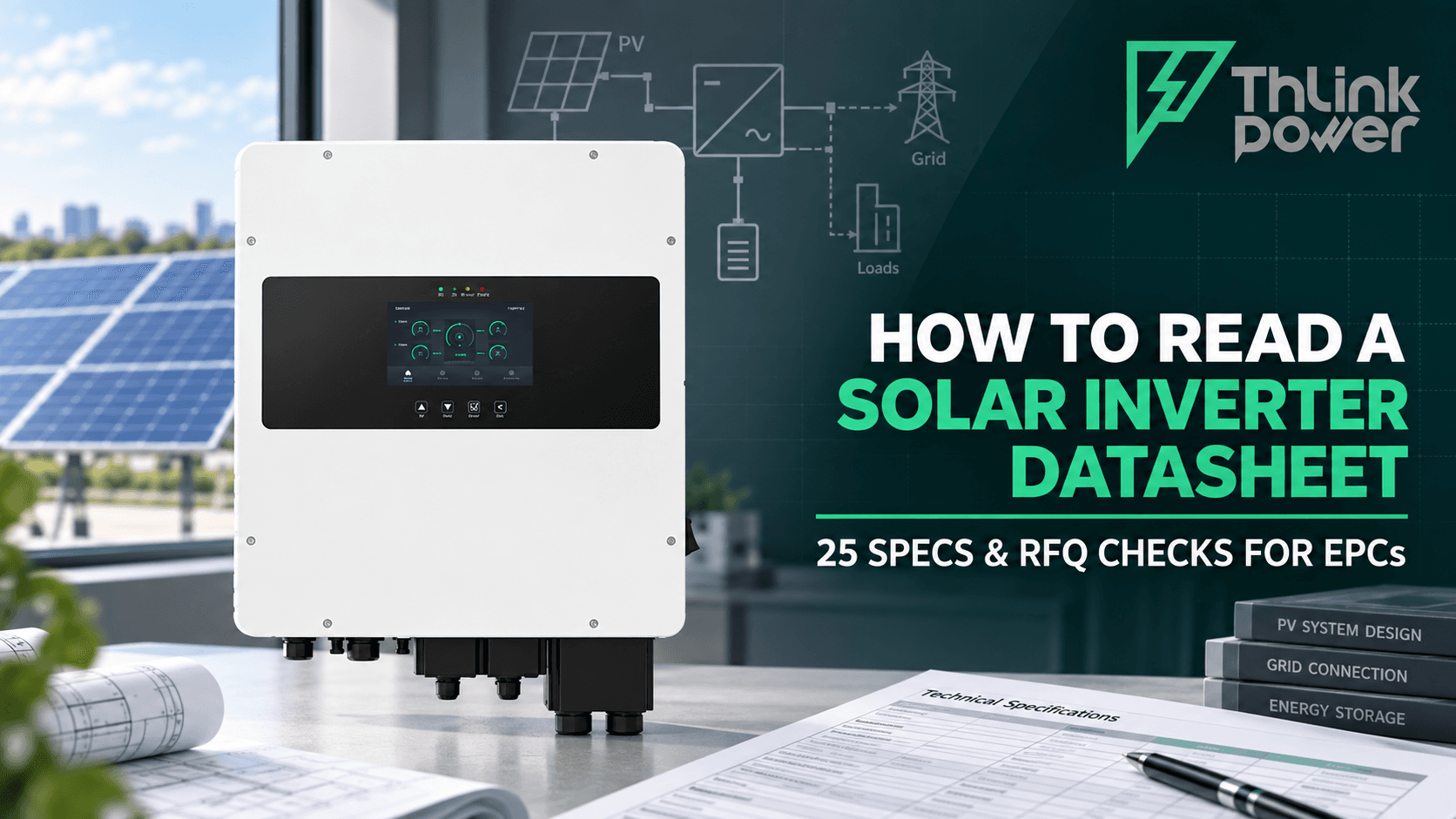
How to Read a Solar Inverter Datasheet: 25 Specifications and RFQ Checks
A practical B2B guide for EPCs and distributors to verify solar inverter voltage, MPPT, current, battery, grid-code, certification, warranty, and commissioning requirements before issuing an RFQ.

Commercial Solar System vs Grid, Diesel and PPA: B2B Decision Guide
A B2B decision guide comparing owned commercial solar, solar PPAs, grid-only power, diesel generation and solar-plus-storage by cost, risk, resilience, contracts, acceptance testing and RFQ scope.

Wholesale Solar Panels Container Guide: Packing, QC & Landed Cost
A distributor and EPC guide to wholesale solar module selection, container packing, landed cost, flash and EL records, pre-shipment inspection, arrival QC, traceability and RFQ controls.
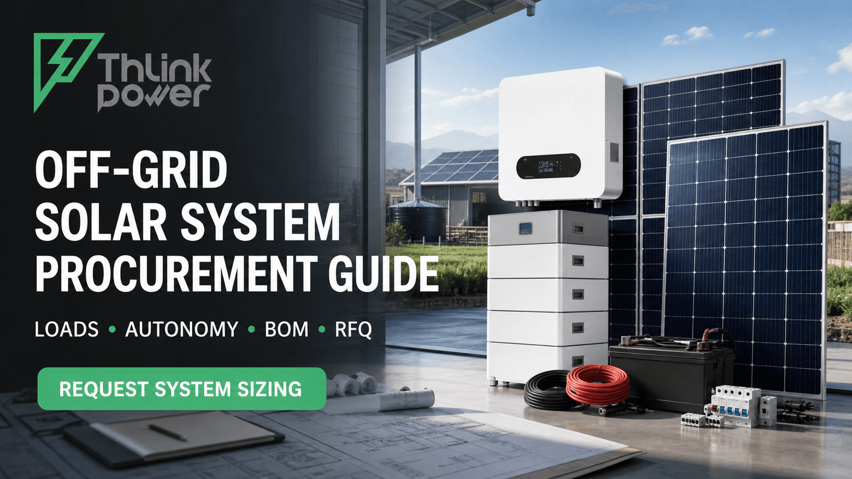
Off-Grid Solar System Procurement Guide: Sizing, BOM & RFQ
A practical B2B guide to off-grid solar load audits, autonomy, PV and battery sizing, inverter selection, generator integration, BOM control, FAT/SAT and a procurement-ready RFQ.